
- Pipelines
- Heat Exchangers
- Fired Equipment
- Columns
- Valves
- Storage
1- Shell & Tube Heat Exchangers
2- Plate & Frame Heat Exchangers
3- Air Cooled Heat Exchangers
4- Spiral Heat Exchangers
Key Terms
Baffles—evenly spaced partitions in a shell-and-tube heat exchanger that support the tubes, prevent vibration, control fluid velocity and direction, increase turbulent flow, and reduce hot spots.
Counterflow—refers to the movement of two flow streams in opposite directions; also called countercurrent flow.
Crossflow—refers to the movement of two flow streams perpendicular to each other.
Differential pressure—the difference between inlet and outlet pressures; represented as ΔP, or delta p.
Differential temperature—the difference between inlet and outlet temperature; represented as ΔT, or delta t.
Fouling—buildup on the internal surfaces of devices such as cooling towers and heat exchangers, resulting in reduced heat transfer and plugging.
Multipass heat exchanger—a type of shell-and-tube heat exchanger that channels the tubeside flow across the tube bundle (heating source) more than once.
Sensible heat—heat that can be measured or sensed by a change in temperature.
Shell-and-tube heat exchanger—a heat exchanger that has a cylindrical shell surrounding a tube bundle.
Shell side—refers to flow around the outside of the tubes of a shell-and-tube heat exchanger.
Thermosyphon reboiler—a type of heat exchanger that generates natural circulation as a static liquid is heated to its boiling point.
Tube sheet—a flat plate to which the ends of the tubes in a heat exchanger are fixed by rolling, welding, or both.
Tube side—refers to flow through the tubes of a shell-and-tube heat exchanger.
Introduction
Heat transfer is an important function of many industrial processes. Heat exchangers are widely used to transfer heat from one process to another. A heat exchanger allows a hot fluid to transfer heat energy to a cooler fluid through conduction and convection. A heat exchanger provides heating or cooling to a process. A wide array of heat exchangers has been designed and manufactured for use in the chemical processing industry.
Classification
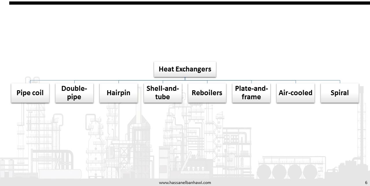
1. Pipe Coil Heat Exchangers
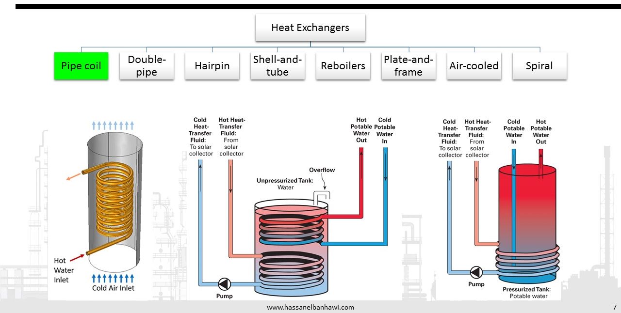
In pipe coil exchangers, pipe coils are submerged in water or sprayed with water to transfer heat. This type of operation has a low heat transfer coefficient and requires a lot of space. It is best suited for condensing vapors with low heat loads.
2. Double Pipe Heat Exchangers
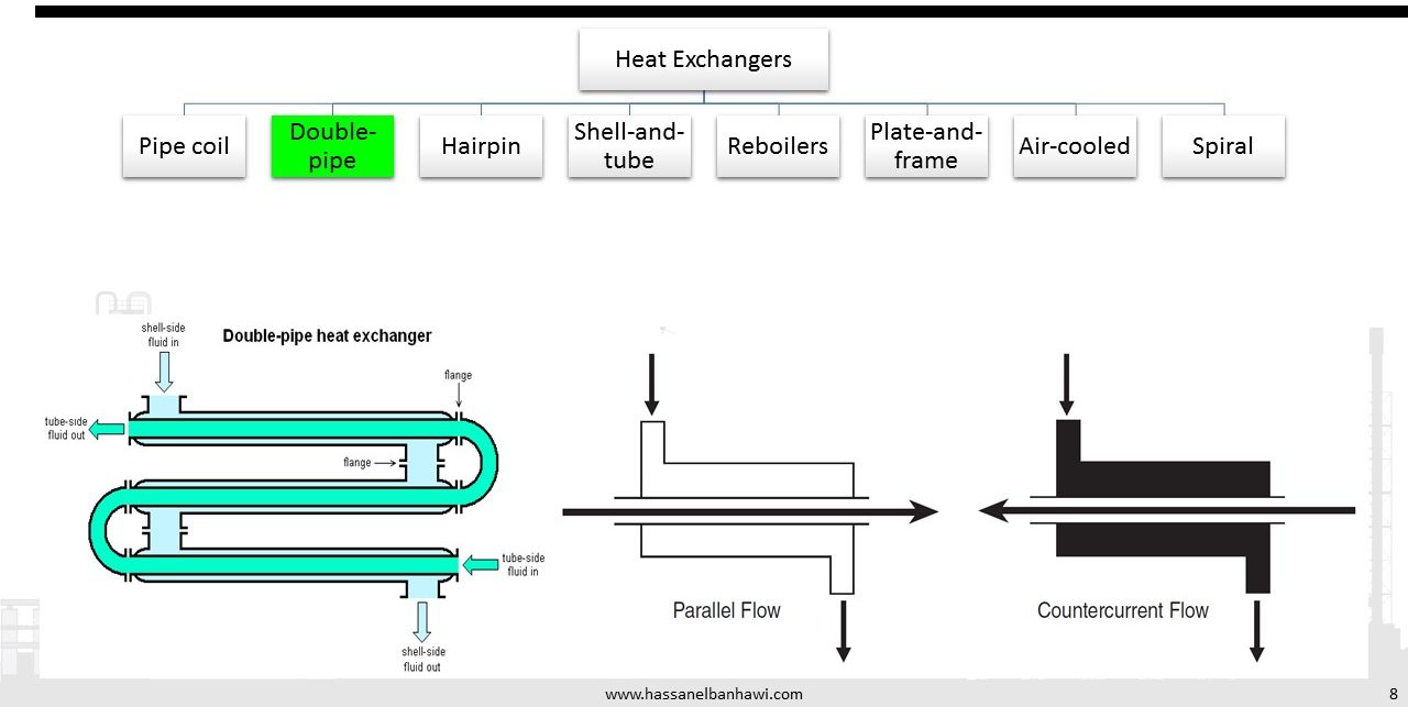
A simple design for heat transfer is found in a double-pipe heat exchanger. A double-pipe exchanger has a pipe inside a pipe. The outside pipe provides the shell, and the inner pipe provides the tube. The warm and cool fluids can run in the same direction (parallel flow) or in opposite directions (counterflow or countercurrent).
Flow direction is usually countercurrent because it is more efficient. This efficiency comes from the turbulent, against-the-grain, stripping effect of the opposing currents. Even though the two liquid streams never come into physical contact with each other, the two heat energy streams (cold and hot) do encounter each other. Energy-laced, convective currents mix within each pipe, distributing the heat.
In a parallel flow exchanger, the exit temperature of one fluid can only approach the exit temperature of the other fluid. In a countercurrent flow exchanger, the exit temperature of one fluid can approach the inlet temperature of the other fluid. Less heat will be transferred in a parallel flow exchanger because of this reduction in temperature difference. Static films produced against the piping limit heat transfer by acting like insulating barriers. The liquid close to the pipe is hot, and the liquid farthest away from the pipe is cooler. Any type of turbulent effect would tend to break up the static film and transfer heat energy by swirling it around the chamber. Parallel flow is not conducive to the creation of turbulent eddies.
3. Hairpin Heat Exchangers
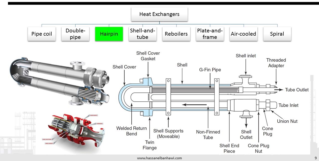
The chemical processing industry commonly uses hairpin heat exchangers. Hairpin exchangers use two basic modes: double-pipe and multipipe design. The exchanger takes its name from its unusual hairpin shape. The double-pipe design consists of a pipe within a pipe. Fins can be added to the internal tube’s external wall to increase heat transfer. The multipipe hairpin resembles a typical shell-and-tube heat exchanger, stretched and bent into a hairpin.
The hairpin design has several advantages and disadvantages. Among its advantages are its excellent capacity for thermal expansion because of its U-tube type shape; its finned design, which works well with fluids that have a low heat transfer coefficient; and its high pressure on the tube side. In addition, it is easy to install and clean; its modular design makes it easy to add new sections; and replacement parts are inexpensive and always in supply. Among its disadvantages are the facts that it is not as cost effective as most shell-and-tube exchangers and it requires special gaskets.
4. Shell and Tube Heat Exchangers
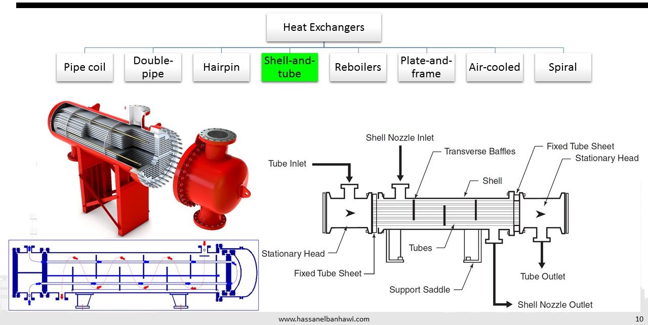
The shell-and-tube heat exchanger is the most common style found in industry. A shell-and-tube heat exchanger has a cylindrical shell that surrounds a tube bundle. Fluid flow through the exchanger is referred to as tubeside flow or shell-side flow. A series of baffles support the tubes, direct fluid flow, increase velocity, decrease tube vibration, protect tubing, and create pressure drops. Shell-and-tube heat exchangers can be classified as fixed head, single pass; fixed head, multipass; floating head, multipass; or U-tube. On a fixed head heat exchanger, tube sheets are a ttached to the shell. Fixed head heat exchangers are designed to handle temperature differentials up to 200°F (93.33°C). Thermal expansion prevents a fixed head heat exchanger from exceeding this differential temperature. It is best suited for condenser or heater operations. Floating head heat exchangers are designed for high temperature differentials above 200°F (93.33°C). During operation, one tube sheet is fixed and the other “floats” inside the shell. The floating end is not attached to the shell and is free to expand.
Shell-and-tube heat exchangers are designed to handle high flow rates in continuous operations. Tube arrangement can vary, depending on the process and the amount of heat transfer required. As the tube-side flow enters the exchanger—or “head”—flow is directed into tubes that run parallel to each other. These tubes run through a shell that has a fluid passing through it. Heat energy is transferred through the tube wall into the cooler fluid. Heat transfer occurs primarily through conduction (first) and convection (second). Liquids move from the bottom of the device to the top to remove or reduce trapped vapor in the system. Gases move from top to bottom to remove trapped or accumulated liquids. This standard applies to both tube-side and shell-side flow.
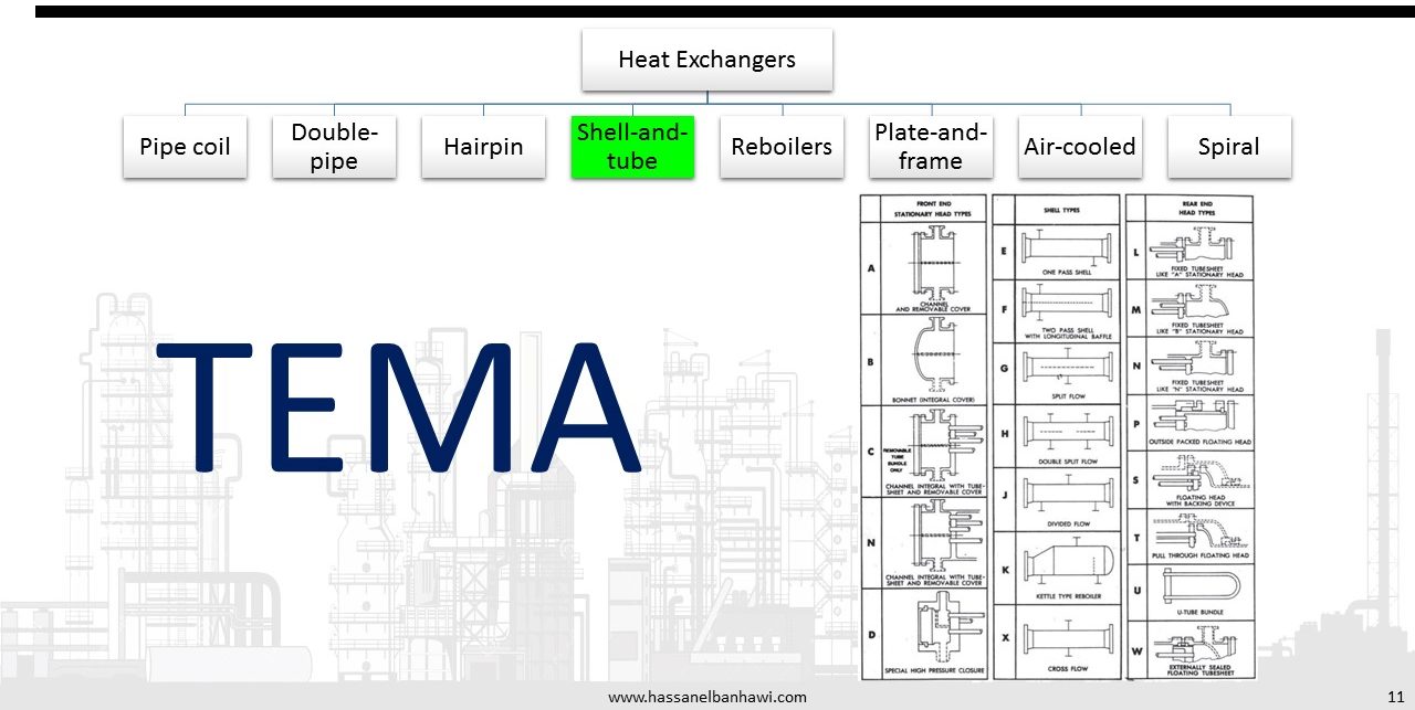
The Tubular Exchanger Manufacturers Association (TEMA) classifies heat exchangers by a variety of design specifications including American Society of Mechanical Engineers (ASME) construction code, tolerances, and
mechanical design:
• Class B, Designed for general-purpose operation (economy and compact design)
• Class C. Designed for moderate service and general-purpose operation (economy and compact design)
• Class R. Designed for severe conditions (safety and durability)
5. Reboilers

Reboilers are used to add heat to a liquid that was once boiling until the liquid boils again. Reboilers are closely associated with the operation of a distillation column. Typical reboiler arrangements include five basic patterns: flooded-tube kettle reboiler, natural circulation, forced circulation, vertical thermosyphon, and horizontal thermosyphon. These types of devices are classified by how they produce fluid flow. If a mechanical
device, such as a pump, is used, the reboiler is referred to as a forced circulation reboiler. Circulation that does not require a pump is classified as natural circulation.
- Kettle Reboiler
Kettle reboilers are shell-and-tube heat exchangers designed to produce a two-phase, vapor-liquid mixture that can be returned to a distillation column. Kettle reboilers have a removable tube bundle that uses steam or a high-temperature process medium to boil the fluid. A large vapor cavity above the heated process medium allows vapors to concentrate. Liquid that does not vaporize flows over a weir and into the liquid outlet.
Hot vapors are sent back to the distillation column through the reboiler’s vapor outlet ports. This process controls the level in the bottom of the distillation column, maintains product purity, strips smaller hydrocarbons from larger ones, and helps maintain the critical energy balance on the column. An important concept with a distillation column is energy or heat balance. Reboilers are used to restore this balance by adding additional heat for the separation processes. Bottom products typically contain the heavier components from the tower. Reboilers take suction off of the bottom products and pump them through their system. Column temperatures are controlled at established set-points. Product flow enters the bottom shell side of a reboiler. As flow enters the reboiler, it comes into contact with the tube bundle. The tubes have steam or hot fluids flowing through them. As the bottom product comes into contact with the tubes, a portion of the liquid is flashed off (vaporized) and captured in the dome-shaped vapor cavity at the top of the reboiler shell. This vapor is sent back to the tower for further separation. A weir contains the unflashed portion of the liquid in a reboiler. Excess flow goes over the weir and is recirculated through the system. Kettle reboilers are easy to control because circulation and two-phase flow rates are not considerations. - Vertical and Horizontal Thermosyphon Reboilers
A thermosyphon reboiler is a fixed head, single-pass heat exchanger connected to the side of a distillation column. Thermosyphon heat exchangers can be mounted vertically or horizontally. The critical design factor is providing sufficient liquid head in the column to support vapor or liquid flowback to the column. Natural circulation occurs because of the differences in density between the hotter liquid in the reboiler and the liquid in the distillation tower. One side of the exchanger is used for heating, usually with steam or hot oil; the other side takes suction off the column. When steam is used as the heated medium in a vertical exchanger, it enters from the top shell inlet and flows downward to the shell outlet, to allow for the removal of condensate. The lower tube inlet of the exchanger usually takes suction at a point low enough on the column to provide a liquid level to the exchanger. A pump is not connected to the column and exchanger unless a forced circulation system is required. This system uses buoyancy forces to flash off and pull in liquid. Newton’s third law of motion, which states that for every action there is an equal and opposite reaction, is a basic operating principle of thermosyphon reboilers. As liquids and vapor circulate back to the column, the inlet line provides fresh liquid to support the circulation. - Stab-In Reboiler
The stab-in reboiler is mounted directly into the base of the distillation column. Steam or hot oil is used as the heating medium. Heat energy is transferred directly into the process medium. The lower section on a distillation column is specially designed to allow the bottom product to boil. This lower section maintains a liquid seal as hot vapors move up the column and heavy liquids collect in the bottom.
6. Plate and Frame Heat Exchangers
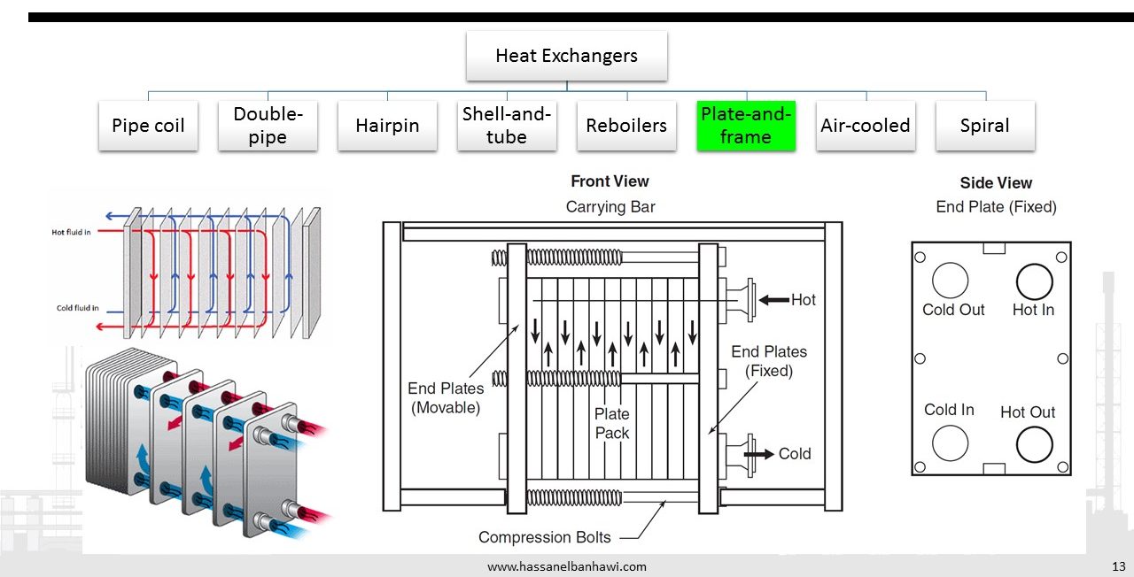
Plate-and-frame heat exchangers are high heat transfer and high pressure drop devices. They consist of a series of gasketed plates, sandwiched together by two end plates and compression bolts. The channels between the plates are designed to create pressure drop and turbulent flow so high heat transfer coefficients can be achieved.
The openings on the plate exchanger are located typically on one of the fixed-end covers. As hot fluid enters the hot inlet port on the fixed-end cover, it is directed into alternating plate sections by a common discharge header. The header runs the entire length of the upper plates. As cold fluid enters the countercurrent cold inlet port on the fixed-end cover, it is directed into alternating plate sections. Cold fluid moves up the plates while hot fluid drops down across the plates. The thin plates separate the hot and cold liquids, preventing leakage.
Fluid flow passes across the plates one time before entering the collection header. The plates are designed with an alternating series of chambers. Heat energy is transferred through the walls of the plates by conduction and into the liquid by convection. The hot and cold inlet lines run the entire length of the plate heater and function like a distribution header. The hot and cold collection headers run parallel and on the opposite side of the plates from each other. The hot fluid header that passes through the gasketed plate heat exchanger is located in the top. This arrangement accounts for the pressure drop and turbulent flow as fluid drops over the plates
and into the collection header. Cold fluid enters the bottom of the gasketed plate heat exchanger and travels countercurrent to the hot fluid. The cold fluid collection header is located in the upper section of the exchanger.
Plate-and-frame heat exchangers have several advantages and disadvantages. They are easy to disassemble and clean and distribute heat evenly so there are no hot spots. Plates can easily be added or removed. Other advantages of plate-and-frame heat exchangers are their low fluid resistance time, low fouling, and high heat transfer coefficient. In addition, if gaskets leak, they leak to the outside, and gaskets are easy to replace. The plates prevent cross-contamination of products. Plate-and-frame heat exchangers provide high turbulence and a large pressure drop and are small compared with shell-and-tube heat exchangers.
Disadvantages of plate-and-frame heat exchangers are that they have high-pressure and high-temperature limitations. Gaskets are easily damaged and may not be compatible with process fluids.
7. Air Coolers
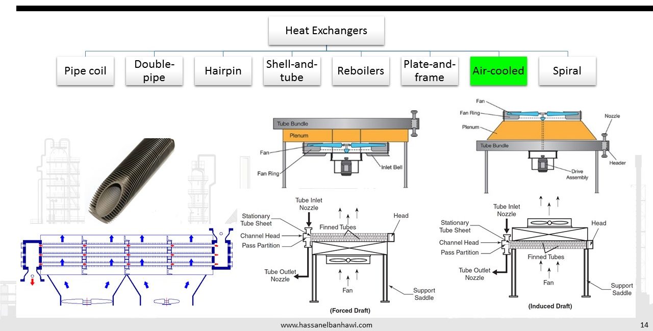
A different approach to heat transfer occurs in the fin fan or air-cooled heat exchanger. Air-cooled heat exchangers provide a structured matrix of plain or finned tubes connected to an inlet and return header. Air is used as the outside medium to transfer heat away from the tubes. Fans are used in a variety of arrangements to apply forced convection for heat transfer coefficients. Fans can be mounted above or below the tubes in forced-draft or induced-draft arrangements. Tubes can be installed vertically or horizontally.
The headers on an air-cooled heat exchanger can be classified as cast box, welded box, cover plate, or manifold. Cast box and welded box types have plugs on the end plate for each tube. This design provides access for cleaning individual tubes, plugging them if a leak is found, and rerolling to tighten tube joints. Cover plate designs provide easy access to all of the tubes. A gasket is used between the cover plate and head. The manifold type is designed for high-pressure applications.
Mechanical fans use a variety of drivers. Common drivers found in service with air-cooled heat exchangers include electric motor and reduction gears, steam turbine or gas engine, belt drives, and hydraulic motors. The fan blades are composed of aluminum or plastic. Aluminum blades are designed to operate in temperatures up to 300°F (148.88°C), whereas plastic blades are limited to air temperatures between 160°F and 180°F (71.11°C, 82.22°C).
Air-cooled heat exchangers can be found in service on air compressors, in recirculation systems, and in condensing operations. This type of heat transfer device provides a 40°F (4.44°C) temperature differential between the ambient air and the exiting process fluid. Air-cooled heat exchangers have none of the problems associated with water such as fouling or corrosion. They are simple to construct and cheaper to maintain than water-cooled exchangers. They have low operating costs and superior high temperature removal (above 200°F or 93.33°C).
Their disadvantages are that they are limited to liquid or condensing service and have a high outlet fluid temperature and high initial cost of equipment. In addition, they are susceptible to fire or explosion in cases of loss of containment.
8. Spiral Heat Exchangers
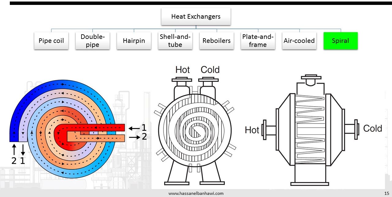
Spiral heat exchangers are characterized by a compact concentric design that generates high fluid turbulence in the process medium. This type of heat exchanger comes in two basic types: (1) spiral flow on both sides and (2) spiral flow–crossflow. Type 1 spiral exchangers are used in liquid-liquid, condenser, and gas cooler service. Fluid flow into the exchanger is designed for full counterflow operation. The horizontal axial installation provides excellent self-cleaning of suspended solids. Type 2 spiral heat exchangers are designed for use as condensers, gas coolers, heaters, and reboilers. The vertical installation makes it an excellent choice for combining high liquid velocity and low pressure drop on the vapor-mixture side. Type 2 spirals can be used in liquid-liquid systems where high flow rates on one side are offset by low flow rates on the other.
References
1-ENGINEERING DATA BOOK by Gas Processors Suppliers Association
2-Process Technology - Equipment and Systems by Charles E. Thomas