
Introduction
Flow regimes and associated pressure drops are complex phenomena and require complex equations to predict their relationships. For engineering design purposes, several empirical formulas have been developed to fit particular circumstances in predicting flow capacity and pressure drop.
In line sizing, consideration shall be given to :
- pressure drop
- velocity
- corrosion/erosion
Where more than one criteria is provided, the most stringent shall govern.
The fluid quantities to be used in determining line sizes shall be those called for by the worst-case maximum process design requirements, considering the full range of operating temperature and pressure conditions.
Classification
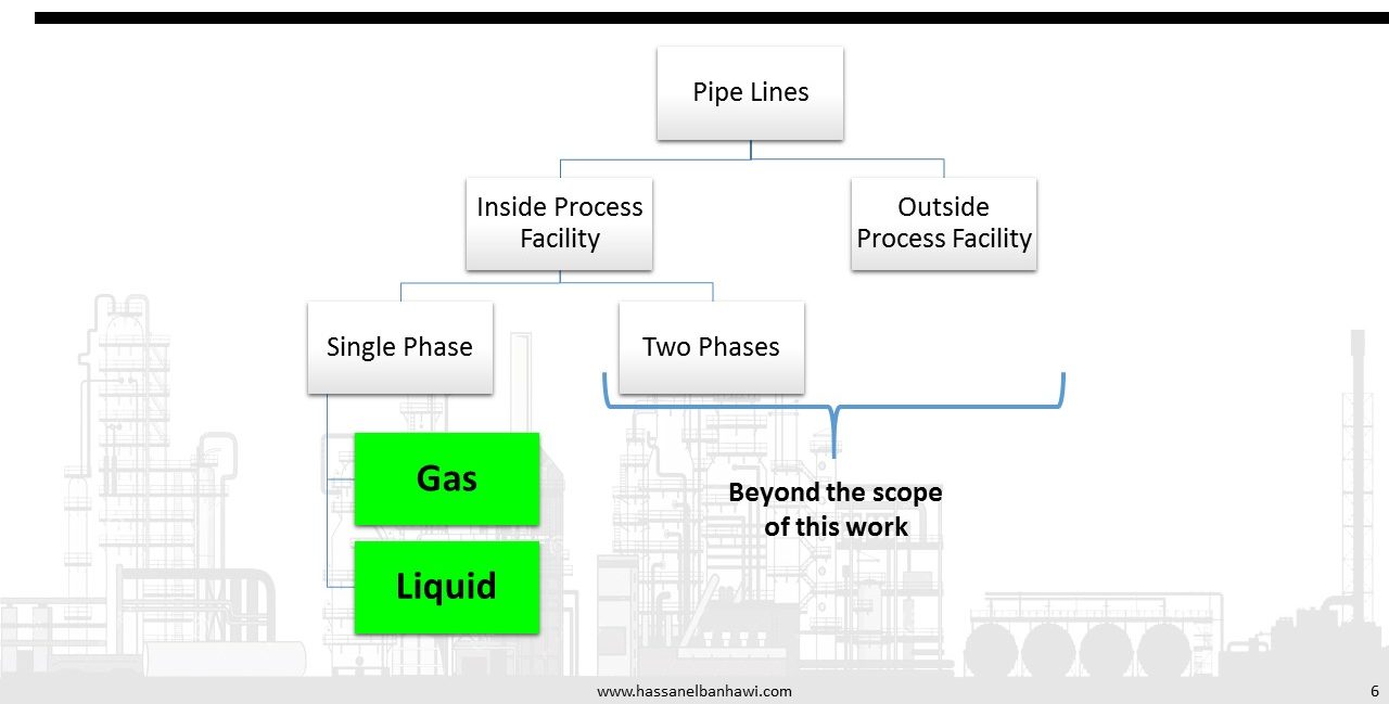
For estimating pressure drop in short runs of gas piping, such as within plant or battery limits, a simplified formula for compressible fluids is accurate for fully turbulent flow, assuming the pressure drop through the line is not a significant fraction of the total pressure (i.e. no more than 10%).
Two-phase flow presents several design and operational difficulties not present in single phase liquid or vapor flow. Frictional pressure drops are much harder to calculate. For cross-country pipelines, a terrain profile is needed to calculate elevation pressure drops. Commercial software is available to simulate these complex two-phase flow situations.
Basics
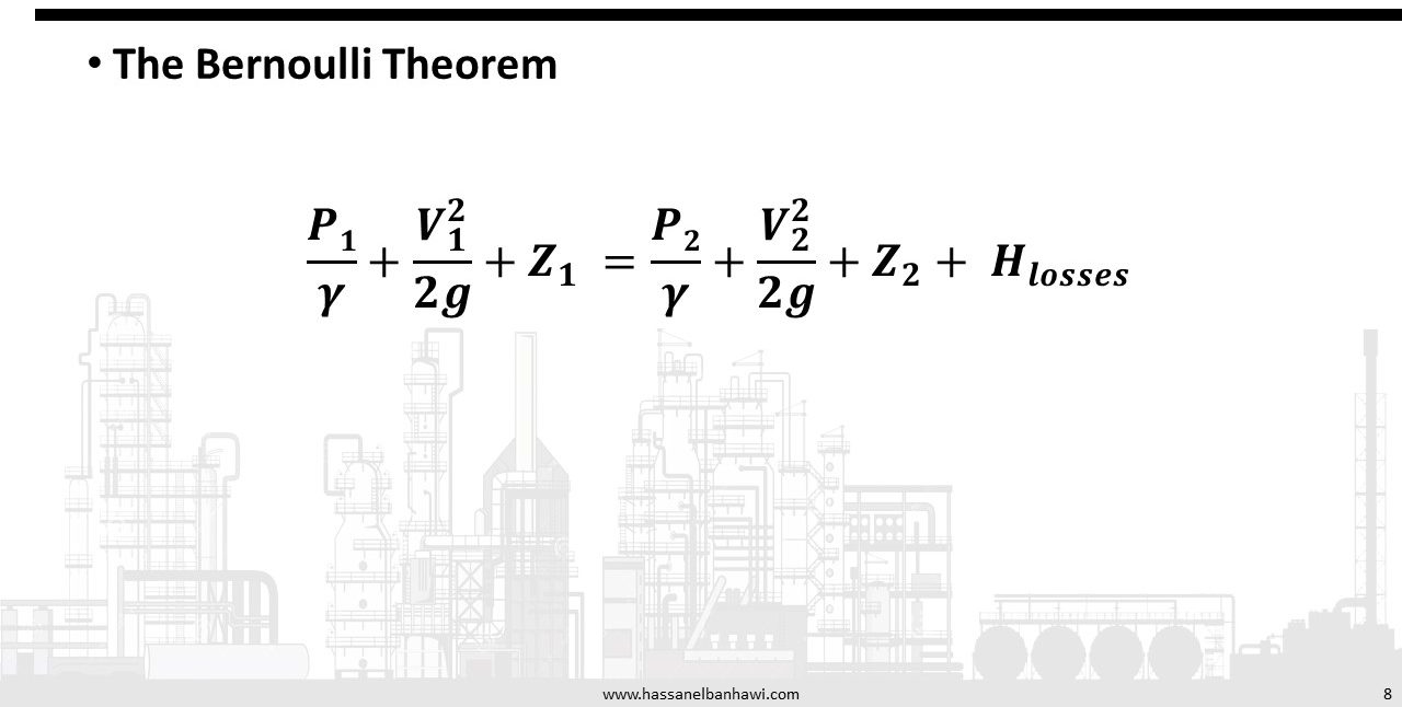
The Bernoulli Theorem is a mathematical derivation based on the law of conservation of energy. This theorem states that the total energy of a fluid at any particular point above a datum plane is the sum of the elevation head, the pressure head, and the velocity head.
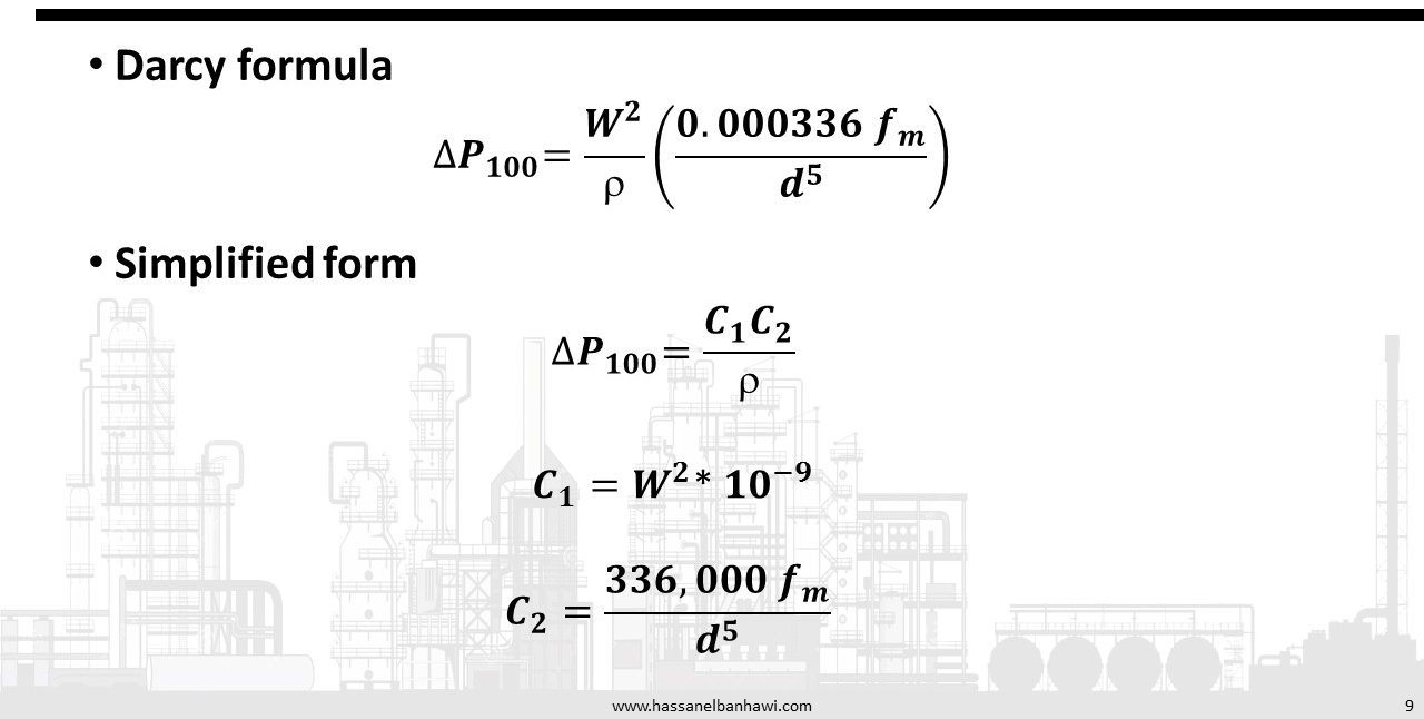
Flow is always accompanied by friction. This friction results in a loss of energy available for work. A general equation for pressure drop due to friction is the Darcy-Weisbach (often referred to as simply the Darcy) equation. This equation can be rationally derived by dimensional analysis, with the exception of the friction factor, fm, which must be determined experimentally.
The Darcy-Weisbach equation is valid for both laminar and turbulent flow of any liquid, and may also be used for gases with certain restrictions. When using this equation, changes in elevation, velocity, or density must be accounted for by applying Bernoulli’s theorem. The Darcy-Weisbach equation must be applied to line segments sufficiently short such that fluid density is essentially constant over that segment. The overall pressure drop is the sum of the Δ Pf values calculated for the individual segments. For gas applications the segmental length may be relatively short, as compared to liquid applications, since many gas applications involve compressible gases where gas densities vary with pressure.
The physical properties of a flowing fluid must be known to predict pressure drop in piping. The two properties entering into the solution of most fluid flow problems are viscosity and density.
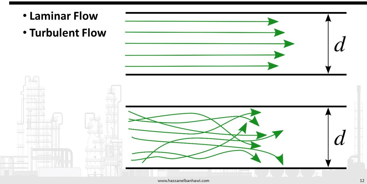
At low velocities, fluid molecules or particles carried by the fluid move in a reasonably straight line. Velocity of the fluid is maximum at the center of the pipe and zero at the pipe wall. This flow pattern is referred to as laminar. If the velocity is increased it will reach a critical point where fluid particles begin to show a random motion transverse to the direction of flow. This is the critical velocity. This random motion is typical of what is referred to as turbulent flow. Above the critical velocity the flow is considered to be completely turbulent even though there is always a boundary layer at the pipe wall where flow is laminar. In the turbulent zone the velocity profile is more nearly straight across the face of the pipe.
Reynolds developed a dimensionless number that may be considered as the ratio of the dynamic forces of mass flow to the shear stress due to viscosity.
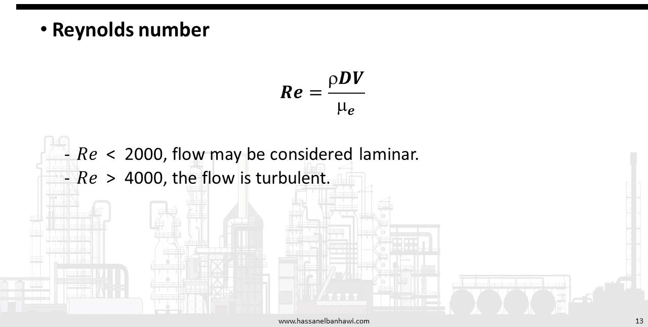
If the Reynolds number is less than 2000, flow may be considered laminar. If it is above 4000, the flow is turbulent. In the zone between 2000 and 4000 the flow could be either turbulent or laminar, but cannot be predicted by the Reynolds number.
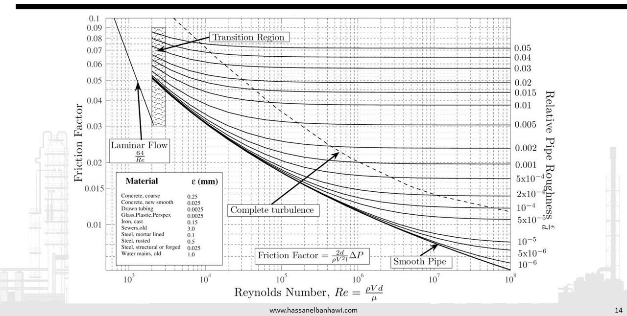
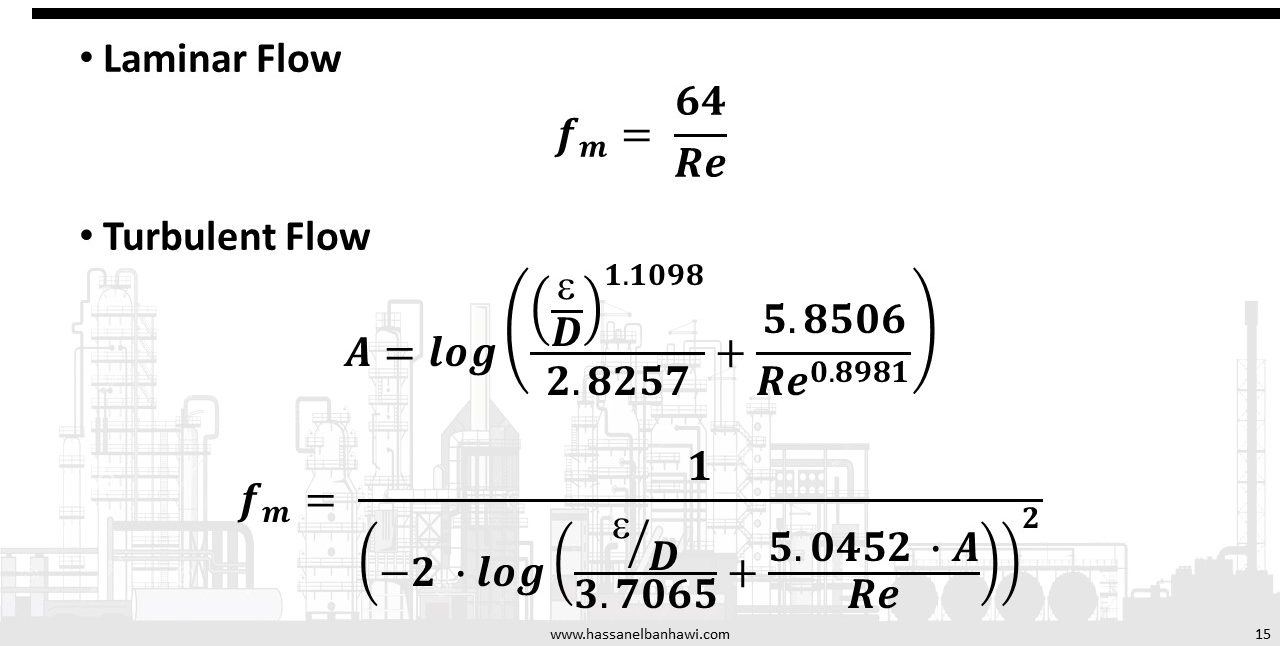
When the fluid flow is laminar (Re<2000), the friction factor has a direct relationship to the Reynolds number, such that: fm = 64 /Re or ff = 16 /Re . Pipe roughness has no effect on the friction factor in laminar flow.
When the flow is turbulent, the friction factor depends on the Reynolds number and the relative roughness of the pipe, ε/D, which is the roughness of the pipe, ε, over the pipe diameter,D.
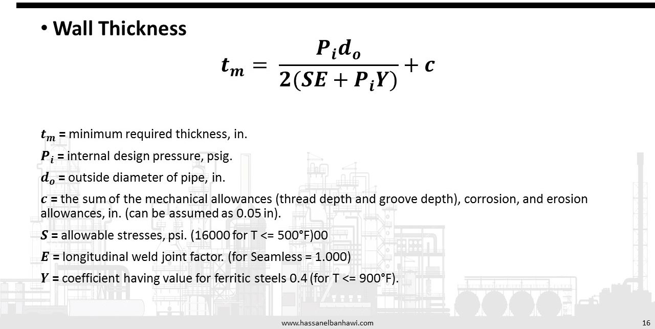
The Pipeline Thickness will determine the allowable internal working pressure for straight sections of pipe in accordance with ANSI B31.3, “Code for Pressure Piping, Petroleum Refinery Piping”.
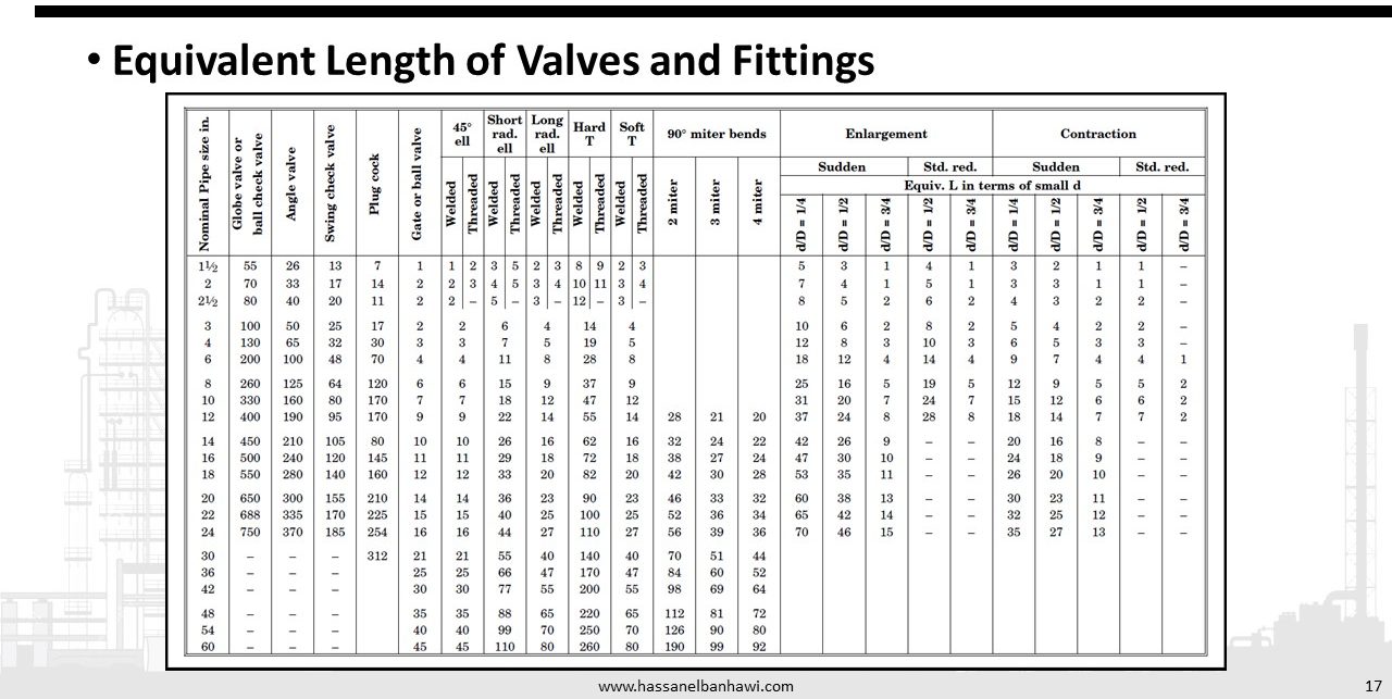
The pressure drop effects of valves and fittings can be accounted for by addition of the “equivalent lengths” of the fittings to the actual piping lengths. This augmented pipe length is then used in any of the following pressure drop calculation techniques.
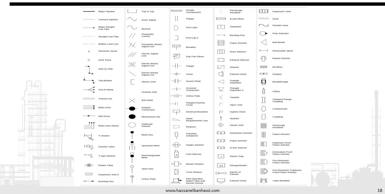
P&ID Symbols
References
1-ENGINEERING DATA BOOK by Gas Processors Suppliers Association
2-Process Technology - Equipment and Systems by Charles E. Thomas